NCT214
http://onsemi.com
14
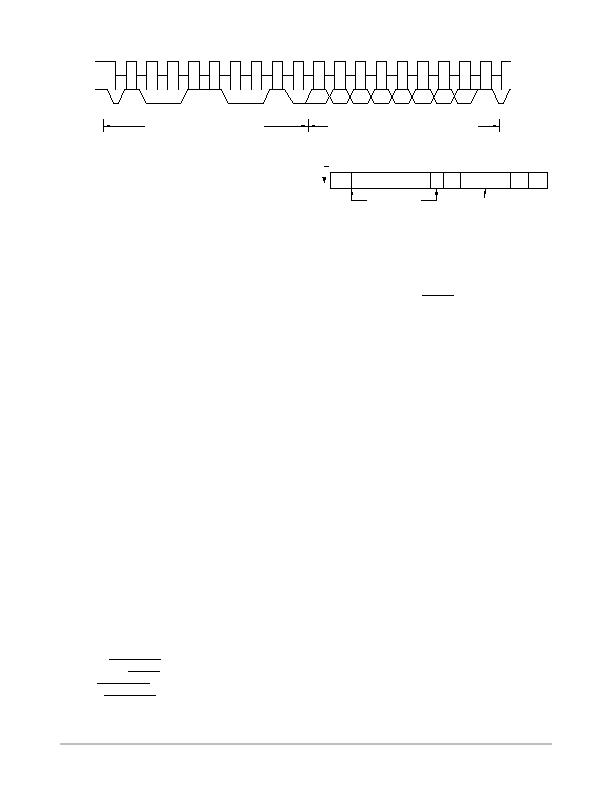
Figure 17. Reading Data from a Previously Selected Register
A6
SCLK
SDATA
A5 A4 A3 A2 A1 A0
D7
D6
D5 D4 D3 D2 D1 D0
ACK. BY
NCT214
STOP BY
MASTER
START BY
MASTER
FRAME 1
SERIAL BUS ADDRESS BYTE
FRAME 2
ADDRESS POINTER REGISTER BYTE
1
1
9
ACK. BY
NCT214
9
R/W
When reading data from a register there are two
possibilities.
" If the address pointer register value of the NCT214 is
unknown or not the desired value, it is first necessary to
set it to the correct value before data can be read from
the desired data register. This is done by writing to the
NCT214 as before, but only the data byte containing
the register read address is sent, because data is not to
be written to the register see Figure 16.
A read operation is then performed consisting of the
serial bus address, R/W
bit set to 1, followed by the
data byte read from the data register see Figure 17.
" If the address pointer register is known to be at the
desired address, data can be read from the
corresponding data register without first writing to the
address pointer register and the bus transaction shown
in Figure 16 can be omitted.
NOTES:It is possible to read a data byte from a data register without
first writing to the address pointer register. However, if the
address pointer register is already at the correct value, it is
not possible to write data to a register without writing to the
address pointer register because the first data byte of a write
is always written to the address pointer register.
Some of the registers have different addresses for read and
write operations. The write address of a register must be
written to the address pointer if data is to be written to that
register, but it may not be possible to read data from that
address. The read address of a register must be written to
the address pointer before data can be read from that
register.
ALERT
Output
This is applicable when Pin 6 is configured as an ALERT
output. The ALERT
output goes low whenever an
out-of-limit measurement is detected, or if the remote
temperature sensor is open circuit. It is an open-drain output
and requires a pullup resistor. Several ALERT
outputs can
be wire-ORed together, so that the common line goes low
if one or more of the ALERT
outputs goes low.
The ALERT
output can be used as an interrupt signal to a
processor, or as an SMBALERT
. Slave devices on the SMBus
cannot normally signal to the bus master that they want to
talk, but the SMBALERT
function allows them to do so.
One or more ALERT
outputs can be connected to a
common SMBALERT
line that is connected to the master.
When the SMBALERT
line is pulled low by one of the
devices, the following procedure occurs (see Figure 18):
Figure 18. Use of SMBALERT
ALERT RESPONSE
ADDRESS
MASTER SENDS
ARA AND READ
COMMAND
DEVICE SENDS
ITS ADDRESS
RD
START
ACK
DEVICE
ADDRESS
NO
ACK
STOP
MASTER RECEIVES SMBALERT
1. SMBALERT
is pulled low.
2. Master initiates a read operation and sends the
alert response address (ARA = 0001 100). This is
a general call address that must not be used as a
specific device address.
3. The device whose ALERT
output is low responds
to the alert response address and the master reads
its device address. As the device address is seven
bits, an LSB of 1 is added. The address of the
device is now known and it can be interrogated in
the usual way.
4. If more than one devices ALERT
output is low,
the one with the lowest device address takes
priority, in accordance with normal SMBus
arbitration.
Once the NCT214 has responded to the alert response
address, it resets its ALERT
output, provided that the error
condition that caused the ALERT
no longer exists. If the
SMBALERT
line remains low, the master sends the ARA
again, and so on until all devices whose ALERT
outputs
were low have responded.
Low Power Standby Mode
The NCT214 can be put into low power standby mode by
setting Bit 6 of the configuration register. When Bit 6 is low,
the NCT214 operates normally. When Bit 6 is high, the
ADC is inhibited, and any conversion in progress is
terminated without writing the result to the corresponding
value register. However, the SMBus is still enabled. Power
consumption in the standby mode is reduced to 5 mA if there
is no SMBus activity, or 30 mA if there are clock and data
signals on the bus.
When the device is in standby mode, it is possible to
initiate a one-shot conversion of both channels by writing to
the one-shot register (Address 0x0F), after which the device
returns to standby. It does not matter what is written to the
one-shot register, all data written to it is ignored. It is also
possible to write new values to the limit register while in
standby mode. If the values stored in the temperature value
发布紧急采购,3分钟左右您将得到回复。
相关PDF资料
NCT72CMNR2G
IC REMOTE THERMAL SENSOR 8-DFN
NCT7491RQR2G
IC REMOTE THERMAL MONITOR 24QSOP
NCT75MNR2G
IC SENSOR TEMP DGTL 8DFN
NCV8881PWR2G
IC REG TRPL BUCK/LINEAR 16SOIC
NE1617ADS,112
IC TEMP MONITOR 16SSOP
NE1619DS,118
IC TEMP MONITOR 16SSOP
NIS5112D1R2G
IC ELECTRONIC FUSE HOTSWAP 8SOIC
NIS5132MN2TXG
IC ELECTRONIC FUSE 12V 10DFN
相关代理商/技术参数
NCT218FCT2G
制造商:ON Semiconductor 功能描述:NCT218 CSP OPN - Tape and Reel 制造商:ON Semiconductor 功能描述:REEL / NCT218 CSP OPN 制造商:ON Semiconductor 功能描述:BATTERY PWR
NCT218MTR2G
制造商:ON Semiconductor 功能描述:LOW VOLTAGE LOCAL TEMPERA - Tape and Reel 制造商:ON Semiconductor 功能描述:REEL / LOW VOLTAGE LOCAL TEMPERA 制造商:ON Semiconductor 功能描述:Low Voltage, High Accuracy Temperature Monitor with I2C Interface
NCT22/D
制造商:未知厂家 制造商全称:未知厂家 功能描述:Low Cost Single Trip Point Temperature Sensor
NCT22DR2
制造商:Rochester Electronics LLC 功能描述:- Bulk 制造商:ON Semiconductor 功能描述:
NCT24DR2
制造商:Rochester Electronics LLC 功能描述:- Bulk
NCT2DC12V
制造商:DBLECTRO 制造商全称:DB Lectro Inc 功能描述:Suitable for automobile, automation system,electronicequipment
NCT3012S TR
制造商:Nuvoton Technology Corp 功能描述:ADVANCED POWER CONTROL IC 制造商:Nuvoton Technology Corp 功能描述:IC PWR SAVING CTLR
NCT3016Y TR
制造商:Nuvoton Technology Corp 功能描述:ADVANCED POWER CONTROL IC 制造商:Nuvoton Technology Corp 功能描述:IC PWR SAVING CTLR